BALTRAD
1. Algorithm name
Correction and quality characterization for attenuation in rain (as a part of RADVOL-QC package) – RADVOL-QC: ATT
2. Basic description
a) Physical basis of the algorithm
Iterative algorithm based on specific attenuation.
b) Amount of validation performed so far
Works operationally in IMGW since 2011 to correct data before using for MeteoFlight system (for air traffic control).
c) References (names and contact information of all developers during the evolutionary history, scientific papers)
- Operational work: IMGW, Department of Ground Based Remote Sensing.
- Scientific paper: Ośródka, K., Szturc, J., and Jurczyk, A., 2012. Chain of data quality algorithms for 3-D single-polarization radar reflectivity (RADVOL-QC system). Meteorol. Appl. (Early View).
3. ODIM metadata requirements for I/O
- General “what”: source(NOD).
- Dataset-specific “what”: gain, offset, nodata, undetect.
- Dataset-specific “where”: nbins, nrays, rscale.
Optional:
- General “how”: wavelength (needed if parameters ATT_a and ATT_b do not exist in XML parameter file).
4. Input data
a) What kind of radar data (including the list of previous algorithms and quality flags applied)
object=PVOL or SCAN; quantity=DBZH, otherwise TH.
b) Other data (optional and mandatory, applying “universally” agreed formats, geometry)
None
5. Logical steps, using any of: text, flow charts, graphics, equations (or references to equations), conditional branches in “all possible cases”.
Algorithm parameters
Set of the algorithm parameters:
| Description | Denotation | Default value |
| Maximum correction for which QIATT = 1 (dB) | ATT_QI1 | 1.0 |
| Minimum correction for which QIATT = 0 (dB) | ATT_QI0 | 5.0 |
| Multiplier of QIATT value for uncorrected attenuation | ATT_QIUn | 0.9 |
| Coefficient a in attenuation formula for X / C / S-bands^*^ | ATT_a | 0.0148 / 0.0044 / 0.0006^#^ |
| Coefficient b in attenuation formula for X / C / S-bands^*^ | ATT_b | 1.31 / 1.17 / 1.00^#^ |
| Coefficient a’’ in ‘‘Z-R formula | ATT_ZRa | 200.0 |
| Coefficient b’’ in ‘‘Z-R formula | ATT_ZRb | 1.6 |
| Minimum reflectivity to apply the correction (dBZ) | ATT_Refl | 4.0 |
| Maximum correction within last km (dB) | ATT_Last | 1.0 |
| Maximum summarized correction (dB) | ATT_Sum | 5.0 |
The radar bands are defined in terms of wavelength as: X: 2.5 - 3.75 cm; C: 3.75 - 7.5 cm, and S: 7.5 - 15.0 cm. Valid in 18°C (Battan, 1973).
At first the XML file is checked whether there exists group for a considered radar (based on the radar name read from “what”/source(NOD)), which contains the algorithm parameters. If “yes”, then parameters are read from that XML group, but if it is impossible for a particular parameter, then default value from source code is taken. If the group does not exist, parameters are read from
The procedure is different in case of ATT_a and ATT_b – if they are not included in relevant XML group for the radar, then those values are deduced from “how”/wavelength. However, if wavelength is not available or is not within 2.5 and 15.0, then the processing is stopped.
If the algorithm is run by means of BALTRAD toolbox then all the algorirthm parameters for each specific radar should be placed in relevant XML file by the BALTRAD system admin. Default parameters are placed in the file by admin as well. Parameters included in HDF5 file are used in cases they are not found in XML file. Moreover, the algorithm default parameters are included in software as well.
Correction
Reflectivity-based algorithm is used iteratively (“gate by gate”) for correction of attenuation in rain.
Attenuation is generally defined as a decrease in radar signal power after passing a meteorological object, that results in underestimation of the measured rain:
where A’’ is the attenuation (in dB); ‘‘Zcor’’ is the non-attenuated reflectivity (in dBZ) and ‘‘Z is the measured one.
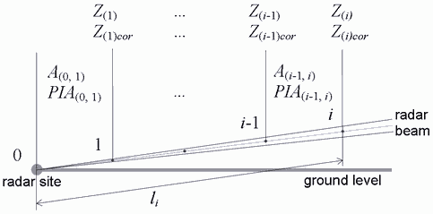
The aim of the algorithm is to calculate the non-attenuated rain. The two-way specific attenuation A’‘(‘‘i’‘-1,’‘i’’) (in dB) in precipitation between measurement gates ‘‘i’‘-1 and ‘‘i can be estimated from the formula:
where R’‘(‘‘i’’) is the precipitation rate in a measurement gate ‘‘i’’ (in mm h^-1^), calculated from reflectivity ‘‘Z (in mm^6^ m^-3^):

The iterative algorithm is employed in the following way. Let us assume that in the previous algorithm steps the specific attenuations _A’‘(0,1) , …, ‘‘A’‘(‘‘i’‘-2,’‘i’‘-1) were calculated as well as their sum ‘‘PIA’‘(0,’‘i_-1), called the path-integrated attenuation:
Firstly, it is checked if the _Z’‘(‘‘i_) value meets the following conditions:
or
Otherwise, i.e. when _Z(i)’’ >= ATT_Refl, from reflectivity ‘‘Z’‘(‘‘i’’) measured in ‘‘i’‘-gate, ‘‘PIA’‘(0,’‘i’‘-1) integrated from the radar site to the ‘‘i’‘-1-gate, and first guess of attenuation ‘‘A’‘’(‘‘i’‘-1,’‘i’’) between ‘‘i’‘-1 and ‘‘i’‘-gates calculated from the above equation for ‘‘A’’, the non-attenuated reflectivity ‘‘Zcor’’(‘‘i_) can be obtained according to the formula:
Then the attenuation A’’,,(‘‘i’‘-1,’‘i’’),, for distance between two neighbouring gates: ‘‘i’‘-1 and ‘‘i’’ can be calculated from the formulas, and consequently path-integrated attenuation along the whole distance from radar site to the given ‘‘i-gate can be obtained from:
This attenuation will be applied in the next step of the iterative algorithm.
In order to avoid instability in the algorithm, certain threshold values have to be set: ATT_Last to limit the corrections for specific attenuation _A’‘(‘‘i’‘-1,’‘i’’), and ATT_Sum for path-integrated attenuation ‘‘PIA’‘(0,’‘i_).
Quality characterization
The magnitude of the attenuation in precipitation PIA’’ (in dB) can be considered as a quality factor for the given measurement gate ‘‘i’’. Therefore the relevant quality index ‘‘QIATT is calculated from the formula:
where parameters ATT_QI1 and ATT_QI0 are empirically determined.
The corrections are employed only if any echo is observed in the given gate, however for quality characterization the data quality decreases behind any echo area for both echo and non-echo gates.
6. Output
a) Data type using ODIM notation where possible, e.g. DBZH
Corrected DBZH, with “pl.imgw.radvolqc.att” added to data-specific “how”/task, and the algorithm parameters added to “how”/task_args.
b) Quality index (QI) field
Quality index (QI 1 for excellent data) with “pl.imgw.radvolqc.att” in quality-specific “how”/task, and the algorithm parameters in “how”/task_args.